Memphis Dock Door Repair Research
Loading Dock Dimensions and Design Calculator
Scope. This page covers the primary dimensions needed to evaluate a loading dock project: platform height, vehicle bed height, door size, bay width, apron depth, approach grade, leveler operating range, pit dimensions, and the number of dock positions. Every retained number travels with its source class, scope, condition, and date. The calculator and dataset are original work; inherited numbers are labeled by source class.
Key findings
Headline finding (DER-FEAS-001):
Using the NOVA NHS hydraulic manual’s maximum ±12-in symmetric range for a vertical-only screen, the cited 36–62-inch preliminary reference envelope cannot be fully spanned at any single dock height: the interval
[62 − 12, 36 + 12] = [50, 48]has no valid solution because 50 > 48. Facility planners should treat this as a prompt to obtain measured fleet data, not as a universal design barrier.
| Dimension topic | What the data show | Source class |
|---|---|---|
| Dock height | GSA L201WH instructional text: “generally 48 in” (GSA-H-001). WBDG: 55 in typical (WBDG-H-001). 7-in gap between two differently scoped references (DER-HEIGHT-001). | Government project template; public-sector design guidance |
| Preliminary truck bed-height envelope | 36–62 in across six vehicle categories from a 2013 manufacturer planning table (NOVA-TRUCK-001). WBDG’s >18-in variation trigger for dock levelers is exceeded by 8 in (WBDG-LEVEL-001, DER-REF-001). | Manufacturer planning guidance (dated 2013) |
| WB-67 apron feasibility screen | 152–157 ft: 2 × 73.5 + 5–10 (DER-WB67-001), applied to FHWA-listed WB-67 overall length of 73.5 ft (FHWA-WB67-001) with the Chalfant rule of thumb (CHALFANT-APRON-001). | Manufacturer rule-of-thumb applied to official design-vehicle geometry |
Source: U.S. General Services Administration, WBDG, NOVA Technology International, Chalfant Dock Equipment, Federal Highway Administration. Last verified July 22, 2026.
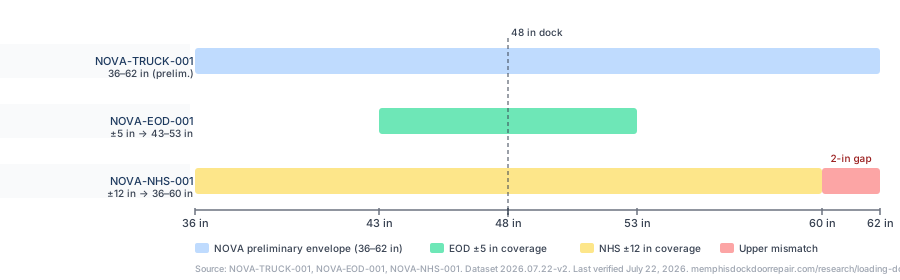
Vertical-range interval comparison at a 48-inch dock
| Vertical range scenario | Range at a 48-in dock | Range span (in) |
|---|---|---|
| NOVA preliminary reference envelope (NOVA-TRUCK-001) | 36–62 in | 26 |
| NOVA Mechanical EOD leveler, ±5-in max (NOVA-EOD-001) | 43–53 in | 10 |
| NOVA NHS Hydraulic leveler, ±12-in max (NOVA-NHS-001) | 36–60 in | 24 |
Source: NOVA Technology International EOD manual (Sept. 2018) and NHS Hydraulic manual (Jan. 2021). Ranges calculated at a 48-in reference dock height. The 60–62-in upper segment of the preliminary envelope is not covered by NHS maximum range at this dock height.
Fleet-Fit Loading Dock Dimension Calculator
The calculator combines entered vehicle measurements, proposed dock and site dimensions, exact equipment limits, and operating assumptions. It exposes every formula, labels every preset by source class, and returns full coverage, partial overlap, missing information, entered activity-share coverage, and project-review triggers. It does not call any result “safe,” “approved,” “compliant,” or “certified.”
Each completed run provides a printable result and a downloadable JSON calculation record containing the entered values, units, assumption labels, formula IDs, source classes, dataset version, verification date, outputs, and every triggered limitation.
U.S. Loading Dock Dimensions Source Matrix, version 2026.07.22-v2
The tables below are the core original compilation behind this page. Stable record IDs preserve the exact source locator, published value, evidence class, scope, and calculator treatment. Derived records then identify the input rows and arithmetic used to produce new results.
Data files: CSV · JSON · Source manifest · Version history · Example calculation record
Evidence classes
| Evidence class | What it means | Calculator treatment |
|---|---|---|
| Federal regulation | A legal requirement within its stated scope and applicability | Apply only after confirming the provision governs the work and operation in question. |
| Local law or official code source | Adopted law, code text, ordinance, or official jurisdictional publication | Verify the currently adopted text, effective date, geography, and project applicability. |
| Government project template or directive | Requirements or editable language for a defined public program | Do not relabel as a nationwide building standard. |
| Public-sector or agency design guidance | Planning guidance published for a public design audience or issued for an agency program | Retain the publisher and scope; do not treat every such reference as an issuing-agency requirement. |
| Official design-vehicle geometry | Vehicle dimensions reproduced by a transportation authority for geometric analysis | Use as a design-vehicle preset only when it represents the vehicles expected at the site. |
| Voluntary consensus standard | A standard covering a defined equipment subject | Applicability may depend on adoption, contract documents, equipment, or governing requirements. |
| Manufacturer planning guidance | Practical, source-specific planning ranges and methods | Treat as dated guidance, not law or national fleet statistics. |
| Product-specific specification | Published dimensions or operating limits for a named product or family | Apply only to the identified model, revision, and configuration. |
| Project measurement or original derivation | A measured project value or a reproducible calculation from disclosed inputs | Preserve the inputs, formula, date, and limitations with the result. |
Source and method: This nine-class framework was created for this dataset to prevent unlike sources from being flattened into a false list of “standard” dimensions.
Source records
| Record ID | Source locator | Variable | Published value | Evidence class | Scope and calculator treatment |
|---|---|---|---|---|---|
| GSA-H-001 | GSA L201WH §3.48 blue instructional text | Trailer-height dock reference | “Generally 48 in” | Government project template | Instructional template text; display as a scoped reference, never an operative universal default |
| GSA-DOOR-001 | GSA L201WH §3.48 operative dock-high-door clause | Dock-high door opening | Minimum 8 ft wide × 10 ft high, approximately 48 in above finished exterior grade | Government project template | Compare with the project's actual usable opening; not a nationwide private-building minimum |
| GSA-DOOR-002 | GSA L201WH §3.48 | Drive-in door opening | Minimum 12 ft wide × 16 ft high | Government project template | Separate opening type; do not merge with dock-high-door values |
| GSA-RAMP-001 | GSA L201WH §3.48 | Drive-in and small-truck/van ramps | Maximum 8.3%, with stricter local code where stated | Government project template | Compare only with the applicable ramp, local requirement, vehicle, and equipment limits |
| GSA-DRAIN-001 | GSA L201WH §3.48 | Loading-area drainage | 1:50, equal to 2% | Government project template | Drainage reference; not a vehicle-operating limit |
| GSA-HEAD-001 | GSA L201WH §3.48 | Loading-berth and apron headroom | Minimum 15 ft | Government project template | Increase may be needed for grade transition and the actual vehicle |
| GSA-BERTH-001 | GSA L201WH loading-berth provisions | Single loading berth width | Minimum 15 ft | Government project template | Subject to the template's local-zoning and agency conditions |
| GSA-BERTH-002 | GSA L201WH loading-berth provisions | Additional contiguous berth width | 12 ft | Government project template | Applies to contiguous additional berths in the template |
| GSA-APRON-001 | GSA L201WH loading-berth provisions | Apron depth | Berth length + 2 ft | Government project template | Source-specific method; retain the berth definition and project scope |
| GSA-APRON-002 | GSA L201WH loading-berth provisions | Apron drainage and grade | Minimum 2% positive drainage; slopes away from dock; maximum 8.3% | Government project template | GSA apron conditions, not a universal equipment or site limit |
| WBDG-H-001 | WBDG, "Loading Dock" | Typical dock height | 55 in above grade | Public-sector design guidance | Compare, but do not convert into a national minimum or an issuing-agency requirement |
| WBDG-LEVEL-001 | WBDG, "Loading Dock" | Bed-height variation trigger | More than 18 in of truck/van variation calls for at least one berth with a dock leveler | Public-sector design guidance | Planning trigger; the exact selected equipment range still governs |
| WBDG-RAMP-001 | WBDG, "Loading Dock" | Delivery ramp | Maximum 1:12, about 8.33% | Public-sector design guidance | Delivery-ramp reference; do not interchange with drainage grades |
| VA-VEH-001 | VA Site Design Manual §4.3.4 | Design vehicle | Service areas should accommodate the largest service vehicle | Public-agency design guidance | Vehicle-selection method for VA projects; the actual project vehicle remains the input |
| VA-TURN-001 | VA Site Design Manual §4.3.4.1, "Refuse Haulers" | Refuse-hauler maneuvering | Turning-movement program; no more than a three-point turn; account for adjacent occupied dock positions | Public-agency design guidance | VA refuse-hauler/dock guidance; do not generalize the three-point-turn criterion to every loading-dock project |
| NOVA-BAY-001 | NOVA Dock Planning Standards, bay-width guidance | Loading bay width | At least 12 ft; 14 ft recommended to reduce congestion | Manufacturer planning guidance | Dated 2013 preliminary reference; compare with actual operations and structure |
| NOVA-CENTER-GENERAL-001 | NOVA Dock Planning Standards, apron-planning guidance | Recommended center distance between dock positions | 12 ft minimum | Manufacturer planning guidance | Dated 2013 apron-planning reference; not a universal code minimum |
| NOVA-CENTER-001 | NOVA Dock Planning Standards, swinging-door guidance | Dock-position center distance where swinging trailer doors operate | At least 14 ft | Manufacturer planning guidance | Source-specific operating condition; not a universal code minimum |
| NOVA-DOOR-001 | NOVA Dock Planning Standards, door guidance | Common and full-access door references | Common: 8 ft wide with 8-, 9-, or 10-ft heights; full access: at least 8 ft 6 in wide and 13–14 ft above driveway | Manufacturer planning guidance | Dated 2013 reference; calculate actual usable clear opening after intrusion |
| NOVA-APRON-001 | NOVA Dock Planning Standards, Table 1 | Typical 40-ft-container-rig apron table | 108–120 ft at 12–18-ft dock centers | Manufacturer planning guidance | Preserve as a discrete source scenario; do not interpolate into a universal requirement |
| NOVA-TRUCK-001 | NOVA Dock Planning Standards, Table 4 | Preliminary six-category bed-height envelope | 36–62 in | Manufacturer planning guidance | Dated 2013 preliminary reference preset; replace with measured vehicles before final use |
| CHALFANT-APRON-001 | Chalfant, "Loading Dock Apron Space" | Apron feasibility screen | 2 × total tractor-and-trailer length + 5–10 ft | Manufacturer planning guidance | Rule-of-thumb screening only; final design requires the actual vehicle and swept path |
| FHWA-WB67-001 | FHWA Highway-Rail Crossing Handbook, Table B-3 | "WB-65 or WB-67" interstate-semitrailer row | 73.5 ft overall; double-asterisk footnote identifies the 53-ft-trailer design vehicle | Official design-vehicle geometry | Optional design-vehicle preset; use only when representative of the project vehicle |
| ECFR-WIDTH-001 | 23 CFR 658.15 | National Network vehicle-width context | Generally 102 in, with stated exceptions and permits | Federal regulation | Vehicle-envelope context only; not a dock-door requirement |
| OSHA-26-001 | 29 CFR 1910.26 | Dockboard duties | Capacity, run-off protection, securement, vehicle-movement measures, and handling | Federal regulation | Safety duties within the provision's scope; no universal dock height, door, bay, or apron value |
| OSHA-28-001 | 29 CFR 1910.28(b)(4) | Dockboard fall-protection threshold | 4 ft or more, with a stated motorized-material-handling exception involving exposure not greater than 10 ft and training conditions | Federal regulation | Fall-protection scope; neither number is a standard platform height |
| OSHA-178-001 | 29 CFR 1910.178(k) and (m) | Powered-industrial-truck loading operations | Brakes/chocks, semitrailer support, safe distance from dock edges, and sufficient headroom | Federal regulation | Operational duties; not a complete geometric design standard |
| MHI-LODEM-001 | MHI LODEM standards registry | Current listed dock-equipment standards | ANSI MH30.1-2022, MH30.2-2022, and MH30.3-2022 | Voluntary consensus standard | Identifies current editions and subjects; clause-level requirements require the standard text and applicability review |
| MEM-UDC-001 | Develop 901 UDC portal | Memphis/Shelby County local-code verification | UDC is the zoning and subdivision code for Memphis and unincorporated Shelby County; portal displays a “UDC Update 2025/2026” link | Local law or official code source | Verification trigger only; the portal does not establish a universal local loading-dock geometry |
| NOVA-EOD-001 | NOVA Mechanical EOD manual, Sept. 2018 | Edge-of-dock leveler range | Maximum ±5-in height difference | Product-specific specification | Applies only to the named document and configuration; service height may vary with design specifications |
| NOVA-NHS-001 | NOVA NHS Hydraulic manual, Jan. 2021 | Hydraulic leveler range | Designed to compensate for a maximum ±12-in height difference, or 24 in total | Product-specific specification | Applies only to the named document and configuration; service height may vary with design specifications |
| BG-M-001 | Blue Giant Model M specification | Pit sizes and working range | Widths 74/80/85 in; lengths 63/87/111 in; front/rear depths 20/19.5 in; range 12 in above and 12 in below | Product-specific specification | Named product-family example; use the selected model's current submittal for construction |
Derived records
| Record ID | Input records | Reproducible calculation | Original result | What the result does — and does not — mean |
|---|---|---|---|---|
| DER-HEIGHT-001 | GSA-H-001 + WBDG-H-001 | 55 − 48 | 7 in | Measures variation between two differently scoped references; it is not an allowable construction tolerance |
| DER-REF-001 | NOVA-TRUCK-001 | 62 − 36 | 26 in | Describes this 26-inch preliminary reference envelope, not every U.S. vehicle or an observed fleet |
| DER-FEAS-001 | NOVA-TRUCK-001 + NOVA-NHS-001 | [62 − 12, 36 + 12] = [50, 48] | No feasible single-height interval | Using the manual's maximum symmetric range for a vertical-only screen, the lower bound exceeds the upper bound; this does not establish full product compatibility |
| DER-WB67-001 | FHWA-WB67-001 + CHALFANT-APRON-001 | 2 × 73.5 + 5–10 | 152–157 ft | Manufacturer-guideline feasibility screen, not a universal truck-court requirement |
| DER-DOOR-001 | ECFR-WIDTH-001 + entered 3-in allowance per side | 102 + 3 + 3 | 108 in, or 9 ft | Transparent opening screen; the side allowance is an editorial assumption, not a legal requirement |
| DER-OPENING-001 | 108-in nominal opening + entered 4-in intrusion per side | 108 − 4 − 4 | 100 in usable width | Illustrates why nominal and usable opening are different; project hardware and geometry govern |
| DER-BAYS-001 | NOVA-CENTER-001 + a 9-ft entered opening | (4 − 1) × 14 + 9 | 51 ft | Outer edge of first opening to outer edge of last, before project-specific end clearances |
| DER-DEMAND-001 | NOVA’s 36-truck worked example | ceiling((36 ÷ 8) × 0.75) and ceiling((36 ÷ 4) × 0.75) | 4 positions over 8 hr; 7 over 4 hr | Baseline concurrency result only; it is not a probability-based queue model |
Source and attribution: U.S. General Services Administration, Whole Building Design Guide, Federal Highway Administration, eCFR, OSHA, MHI/LODEM, Memphis and Shelby County Develop 901 portal, NOVA Technology International, Blue Giant Equipment Corporation, and Chalfant Dock Equipment. Derived rows use only the disclosed source records and arithmetic shown on this page. Last verified July 22, 2026.[2][3][4][9][8][5][6][7][11][17][12][15][16][14][13]
What does this dataset show — and what does it not show?
This dataset shows the published value, source type, scope, document date or revision, verification date, and calculator role for each retained dimension. It does not certify a design, select equipment, establish local code compliance, or prove that a generic vehicle range describes a particular fleet.
What the dataset shows
- How two public-sector references can use dock-height values seven inches apart without either becoming a universal national standard.
- How preliminary vehicle ranges, fields for actual vehicle measurements, and product operating limits interact.
- Why door width, nominal door size, and usable clear opening are different quantities.
- Why a berth width, loading-bay width, centerline spacing, and total dock-face span should not share one unlabeled "dock width" field.
- Why apron values from different sources cannot be compared honestly without retaining the design vehicle, center spacing, approach geometry, and calculation method.
- Which OSHA provisions address dockboards, falls, vehicle movement, and powered-industrial-truck operations — and which geometric dimensions those provisions do not supply.
What the dataset does not show
- A universal, code-approved platform height.
- A universal clear door opening or leveler pit.
- A complete structural, pavement, drainage, fire, accessibility, or traffic design.
- A probability-based queue model for dock demand.
- A guarantee that a leveler can serve a vehicle merely because the vertical ranges overlap.
- A Memphis or Shelby County approval determination.
Scope finding: Of the nine evidence classes on this page, only one is “federal regulation.” Even then, the reviewed regulations address specific matters such as vehicle width on the National Network, dockboard use, fall protection, and powered-industrial-truck operations. They do not combine into a universal loading-dock geometry.[8][5][6][7]
How was the loading dock dimensions dataset produced?
We built the source matrix by reading current government pages and manuals, public-sector and agency design documents, the official MHI/LODEM standards registry, dated manufacturer planning guides, and exact product documents. We retained a number only when its source, scope, condition, unit, and verification date could travel with it; unsupported “standard” claims were excluded rather than averaged into a cleaner-looking answer.
Source-selection rules
We included a source when it met at least one of these conditions:
- It is the issuing government agency’s current regulation, template, manual, or design page.
- It is the official registry or publisher page for a named consensus standard.
- It is an original planning document published by the manufacturer responsible for it.
- It is an exact product manual or specification published by the manufacturer.
- It supplies an official design-vehicle dimension that can be combined with a clearly disclosed calculation.
We did not use competitor summaries or forum comments as evidence for technical or legal claims. Those sources can reveal the words people use, but they do not establish a dimension.
The 19-field record schema
Each retained row is designed to preserve enough context for another researcher to reproduce or challenge it:
record_id
dimension_category
variable
value_min
value_max
value_text
unit
condition
source_class
source_organization
source_title
source_revision
source_page_or_section
source_url
verified_date
universal_standard
calculator_use
derived_from_record_ids
notes
How source conflicts were handled
We did not average GSA’s approximately 48-inch reference and WBDG’s 55-inch typical value into 51.5 inches. That would create a new number with no issuing source and conceal why the references differ. Instead, the dataset preserves both values, labels their scopes, and calculates only the transparent 7-inch difference (DER-HEIGHT-001). The same rule applies to truck ranges, bay spacing, apron methods, grade guidance, and leveler operating ranges.
Regression tests for the calculator
Every original result on this page uses visible arithmetic or interval logic. These cases are the required regression tests after any source or formula change:
| Regression test | Expected result |
|---|---|
| 55 − 48 | 7 in |
| 62 − 36 | 26 in |
| 48-inch dock with ±5-inch range | 43–53 in |
| 48-inch dock with ±12-inch range | 36–60 in |
| 36–62-inch preliminary reference envelope with ±12-inch range | No feasible single-height interval |
| 2 × 73.5 + 5 | 152 ft |
| 2 × 73.5 + 10 | 157 ft |
| Four 9-foot doors on 14-foot centers | 51 ft before end clearances |
| 36 trucks over 8 hours at 45 minutes each | 4 positions after rounding up |
| 36 trucks over 4 hours at 45 minutes each | 7 positions after rounding up |
Source and method: The source values come from the documents named in the article; the test cases are original reproducibility checks for this dataset and calculator.
How high should a loading dock be?
No single universal height is established by the sources reviewed. Two public-sector references publish values 7 inches apart, and neither is the binding nationwide answer.[2][3]
| Record | Value | Source class | Scope |
|---|---|---|---|
| GSA-H-001 | ≈48 in | Government project template | Instructional blue text in GSA L201WH; not the operative clause; not a nationwide private-building minimum[2] |
| WBDG-H-001 | 55 in | Public-sector design guidance | “Typical” reference on the WBDG Loading Dock page; do not convert to a national minimum[3] |
| DER-HEIGHT-001 | 7 in gap | Publisher derivation | 55 − 48 = 7; scope difference, not an allowable tolerance |
Preliminary truck bed-height envelope
NOVA’s 2013 planning guide (NOVA-TRUCK-001, Table 4) lists six vehicle categories with a combined preliminary outer envelope of 36–62 in. This 26-inch span (DER-REF-001) is dated manufacturer guidance; it is not current national fleet statistics. Replace it with measured values for the specific vehicles that will use the dock.
WBDG notes that more than 18 inches of truck/van variation calls for at least one berth with a dock leveler (WBDG-LEVEL-001). The 26-inch preliminary envelope exceeds that trigger by 8 inches.
Using the NOVA NHS hydraulic manual’s maximum ±12-in symmetric range for a vertical-only screen (DER-FEAS-001): no single dock height covers the full 36–62 in outer envelope. The feasibility interval [62 − 12, 36 + 12] = [50, 48] has no valid solution. Planners should obtain measured fleet data.
What size should a loading dock door be?
Nominal opening and usable clear opening are different values. Hardware, seals, shelters, tracks, and positioning reduce the nominal opening; use the usable clear opening for vehicle and forklift access checks.[2][12]
| Record | Opening type | Width | Height | Source class |
|---|---|---|---|---|
| GSA-DOOR-001 | Dock-high door | 8 ft (96 in) min | 10 ft (120 in) min, ≈48 in above grade | Government project template |
| GSA-DOOR-002 | Drive-in door | 12 ft (144 in) min | 16 ft (192 in) min | Government project template |
| NOVA-DOOR-001 (common) | Common dock door | 8 ft (96 in) | 8, 9, or 10 ft | Manufacturer planning guidance (2013) |
| NOVA-DOOR-001 (full-access) | Full-access door | ≥8 ft 6 in (102 in) | 13–14 ft above driveway | Manufacturer planning guidance (2013) |
| DER-DOOR-001 | Width screen (102-in vehicle + 3 in per side) | 108 in (9 ft) | — | Publisher derivation |
| DER-OPENING-001 | Usable width after 4-in intrusion per side | 100 in | — | Publisher derivation |
Width screen and usable opening
DER-DOOR-001 (9-ft width screen):
  102 in (23 CFR 658.15 National Network vehicle width)
  + 3 in (left clearance — editorial assumption, not a legal requirement)
  + 3 in (right clearance — editorial assumption)
  = 108 in nominal opening screen (9 ft)

DER-OPENING-001 (usable clear width):
  108 in (nominal)
  − 4 in (left seal/hardware intrusion — enter your actual value)
  − 4 in (right seal/hardware intrusion — enter your actual value)
  = 100 in usable clear width
These are illustrative calculations, not minimum clearances. Project hardware, tracks, seals, and positioning govern the actual usable opening.
How wide should loading dock bays and berths be?
Bay width, berth width, and centerline spacing are different quantities; do not use a single number for all three. Sources use different definitions and apply different conditions.[2][12]
| Record | Dimension | Value | Condition | Source class |
|---|---|---|---|---|
| GSA-BERTH-001 | Single loading berth width | 15 ft min | GSA template scope | Government project template |
| GSA-BERTH-002 | Additional contiguous berth width | 12 ft | Contiguous berths only | Government project template |
| NOVA-BAY-001 | Loading bay width | ≥12 ft; 14 ft recommended | 2013 preliminary reference | Manufacturer planning guidance |
| NOVA-CENTER-GENERAL-001 | Center distance | 12 ft minimum | Apron-planning section | Manufacturer planning guidance (2013) |
| NOVA-CENTER-001 | Center distance | ≥14 ft | Swinging trailer doors | Manufacturer planning guidance (2013) |
| DER-BAYS-001 | Four-bay dock-face span at 14-ft centers | 51 ft before end clearances | (4−1)×14+9 ft | Publisher derivation |
Dock-face span example
DER-BAYS-001: Four dock positions at 14-ft centers with a 9-ft entered opening
  (4 − 1) × 14 ft + 9 ft = 51 ft
  Before end clearances, columns, control panels, and project-specific additions
How much apron or truck-court depth does a loading dock need?
Three source methods are present in this dataset. They use different design vehicles, different center spacings, and different calculation methods; they cannot be directly compared.[2][12][13][9]
| Record | Method | Input | Output | Source class |
|---|---|---|---|---|
| GSA-APRON-001 | Berth length + 2 ft | Berth length | Project-specific | Government project template |
| NOVA-APRON-001 | Table 1 (40-ft container rig, 12–18-ft centers) | Container rig | 108–120 ft | Manufacturer planning guidance (2013) |
| CHALFANT-APRON-001 | 2 × total L + 5–10 ft | Overall vehicle length | Project-specific screen | Manufacturer planning guidance |
| DER-WB67-001 | Chalfant rule applied to FHWA WB-67 (73.5 ft) | 73.5-ft WB-67 | 152–157 ft | Publisher derivation |
WB-67 apron feasibility screen
DER-WB67-001:
  FHWA-WB67-001: WB-65/WB-67 overall length = 73.5 ft (double-asterisk: 53-ft trailer design vehicle)
  CHALFANT-APRON-001: apron screen = 2 × total length + 5 to 10 ft

  Lower screen: 2 × 73.5 + 5  = 152 ft
  Upper screen: 2 × 73.5 + 10 = 157 ft

  This is a manufacturer rule-of-thumb feasibility screen, not a universal truck-court requirement.
  Final design requires the actual design vehicle and swept-path analysis.
How do approach grade and drainage change loading dock dimensions?
Different grade values in this dataset apply to different surfaces and different regulatory conditions. Always identify the applicable surface, vehicle, equipment limit, and source before using a percentage.[2][3]
Grade (%) = 100 × rise (in) / (run (ft) × 12)| Record | Grade value | Surface or condition | Source class |
|---|---|---|---|
| GSA-DRAIN-001 | 2% (1:50) | Loading-area drainage | Government project template |
| GSA-RAMP-001 | max 8.3% | Drive-in and small-truck/van ramps (stricter local code where stated) | Government project template |
| GSA-APRON-002 | 2% min, 8.3% max | Apron drainage and grade | Government project template |
| WBDG-RAMP-001 | max 8.33% (1:12) | Delivery ramp | Public-sector design guidance |
Source: GSA Warehouse Lease Template L201WH (May 2025); WBDG Loading Dock. Each grade applies only to its named surface and condition.
What dock leveler range and pit size are required?
There is no single leveler range or pit size that applies to every project. Each product-specific specification governs only the named model, revision, and configuration.[15][16][14]
| Record | Product type | Above-dock range (A) | Below-dock range (B) | Coverage at 48-in dock | Limitation |
|---|---|---|---|---|---|
| NOVA-EOD-001 | NOVA Mechanical EOD | ±5 in | ±5 in | 43–53 in | Named product only; service height may vary |
| NOVA-NHS-001 | NOVA NHS Hydraulic | ±12 in | ±12 in | 36–60 in | Named product only; service height may vary |
| BG-M-001 | Blue Giant Model M | ±12 in | ±12 in | 36–60 in | Named product-family example only; use current submittal |
At 48-in dock with NOVA-EOD-001 (±5 in):  43–53 in bed height covered
At 48-in dock with NOVA-NHS-001 (±12 in): 36–60 in bed height covered

DER-FEAS-001 fleet feasibility interval:
  [hMax − A, hMin + B] = [62 − 12, 36 + 12] = [50, 48]
  50 > 48 → no feasible single-height interval using NHS maximum symmetric range
  (using NOVA-TRUCK-001 outer envelope of 36–62 in)
Blue Giant Model M — example pit dimensions
| Pit width (in) | Pit length (in) | Front depth (in) | Rear depth (in) | Working range |
|---|---|---|---|---|
| 74 | 63 | 20 | 19.5 | ±12 in |
| 80 | 87 | 20 | 19.5 | ±12 in |
| 85 | 111 | 20 | 19.5 | ±12 in |
Source: Blue Giant Equipment Corporation, Model M Mechanical Dock Leveler specification (BG-M-001). Named product-family example only. Use the selected model’s current submittal and structural design for construction.
How many loading dock positions does a warehouse need?
A baseline concurrency count can be produced from peak arrival rate and average occupancy time. This is not a probability-based queue model and does not account for arrival bunching, appointment reliability, or service-level targets.[12]
Baseline positions = ceiling(peak trucks per hour × average occupancy hours)

DER-DEMAND-001 — NOVA's worked example:
  36 trucks over 8 hours at 0.75 hr average:
  ceiling((36 ÷ 8) × 0.75) = ceiling(3.375) = 4 positions

  36 trucks over 4 hours at 0.75 hr average:
ceiling((36 ÷ 4) × 0.75) = ceiling(6.75) = 7 positions| Peak rate (trucks/hr) | 0.50 hr avg occupancy | 0.75 hr avg occupancy | 1.00 hr avg occupancy |
|---|---|---|---|
| 3 | 2 | 3 | 3 |
| 4.5 | 3 | 4 | 5 |
| 9 | 5 | 7 | 9 |
Source and method: Formula from NOVA Dock Planning Standards (2013) worked example. Results are ceiling(peakRate × avgOccupancy). Not a probability model.
Which loading dock rules, standards, and guidance apply?
The nine evidence classes used in this dataset describe what each source is — and, more importantly, what it is not. No single source creates a universal loading-dock geometry applicable to every project.[5][6][7][8][11]
| Record | What it addresses | What it does not provide |
|---|---|---|
| OSHA-26-001 | Dockboard capacity, run-off protection, securement, vehicle movement measures, handling | A universal dock height, door size, bay spacing, or apron depth |
| OSHA-28-001 | Fall protection at dockboard height ≥4 ft; motorized-material-handling exception ≤10 ft | A standard platform height (the 4-ft and 10-ft values are fall-protection thresholds, not design heights) |
| OSHA-178-001 | Brakes/chocks, semitrailer support, safe dock-edge distance, headroom for powered trucks | A complete geometric design standard for dock height, door, or bay dimensions |
| ECFR-WIDTH-001 | Vehicle width on the National Network (generally 102 in, with exceptions and permits) | A dock-door minimum width; it is vehicle-envelope context only |
| FHWA-WB67-001 | WB-65 or WB-67 design-vehicle geometry (73.5 ft overall, 53-ft trailer footnote) | A requirement to use this vehicle; it is an optional design-vehicle preset |
| MHI-LODEM-001 | Current editions of ANSI MH30.1, MH30.2, and MH30.3 dock-equipment standards | Clause-level requirements without the standard text; applicability depends on adoption and contract documents |
| MEM-UDC-001 | Identify that the Memphis and Shelby County UDC is the local zoning and code reference | A universal loading-dock geometry; verify the currently adopted text and project applicability |
Why do loading dock dimensions need dated sources?
A dimension without a source date and scope is a claim without a verifiable basis. The source documents on this page range from current federal regulations to a 2013 manufacturer planning guide. An undated number cannot reveal whether its source has been revised.
| Record prefix | Source document date | Source class |
|---|---|---|
| GSA | May 2025 (loading-dock clause: May 2014) | Government project template |
| WBDG | Undated web page | Public-sector design guidance |
| VA | March 2024 | Public-agency design guidance |
| FHWA | Third edition | Official design-vehicle geometry |
| OSHA | Current regulations (continuously updated) | Federal regulation |
| ECFR | Current regulation (continuously updated) | Federal regulation |
| NOVA (planning) | 2013 | Manufacturer planning guidance |
| Chalfant | Undated web page | Manufacturer planning guidance |
| NOVA-EOD | September 2018 | Product-specific specification |
| NOVA-NHS | January 2021 | Product-specific specification |
| BG-M | Undated (verified July 2026) | Product-specific specification |
| MEM-UDC | 2025/2026 update shown on portal | Local law reference |
Dataset version history
| Version | Date | Material change |
|---|---|---|
| 2026.07.21-v1 | 2026-07-21 | Initial source-classified matrix; reference-envelope method; apron screen; door and bay calculations; leveler comparison; position-count example; methodology and limitations |
| 2026.07.22-v2 | 2026-07-22 | Corrected GSA/WBDG/VA/FHWA/Memphis/NOVA bay-center and NHS scopes; moved findings above calculator; added stable record fragments, direct data distributions, interval visualization, entered activity-share coverage, calculation-record requirements, dock-demand sensitivity matrix |
What are the limitations of the dataset and calculator?
- The calculator produces geometric screening results only — not structural, fire, accessibility, zoning, traffic, workplace-safety, equipment-application, permit, code-compliance, or professional-approval determinations.
- Vehicle bed-height ranges labeled "preliminary reference" or "NOVA-TRUCK-001 preset" come from a 2013 manufacturer planning guide; they are not current national fleet statistics and must be replaced with measured data before final design.
- A source record's "vertical range covered" output does not confirm leveler compatibility; lip engagement, capacity, rear-frame geometry, trailer float, end loading, bumper projection, underclearance, gradeability, and restraints are not evaluated.
- The feasibility interval [hMax − A, hMin + B] is a vertical-only screen. It does not evaluate side-to-side alignment, dock door clearance above or beside the leveler, approach grade, or operating method.
- The apron depth screen (2 × L + 5–10 ft) is a single manufacturer's rule of thumb; final truck-court design requires a swept-path analysis for the actual vehicle.
- The baseline dock-position formula is a workload concurrency screen; it is not a probability-based queue model and does not account for arrival bunching, appointment reliability, or service-level targets.
- Grades, headroom, and drainage values from different source rows cannot be combined without verifying that the applicable surface, vehicle, equipment, and regulatory condition are the same.
- OSHA provisions address specific duties (dockboard use, fall protection, powered-industrial-truck operations). They do not state a universal dock height, door size, bay spacing, or apron depth.
- The Memphis/Shelby County UDC is identified as the local code reference, but the portal does not establish a universal loading-dock geometry; verify the currently adopted text, effective date, and project applicability.
- This dataset covers primary geometric dimensions and workload screening only. It does not address pavement, structural, drainage, mechanical, electrical, fire-suppression, ADA accessibility, air quality, or traffic design.
How should this page and dataset be cited?
Article (APA 7th)
Memphis Dock Door Repair Research. (2026, July 22). Loading dock dimensions and
design calculator [Research article]. Memphis Dock Door Repair.
https://memphisdockdoorrepair.com/research/loading-dock-dimensions/
Article (MLA 9th)
Memphis Dock Door Repair Research. "Loading Dock Dimensions and Design
Calculator." Memphis Dock Door Repair, 22 July 2026,
memphisdockdoorrepair.com/research/loading-dock-dimensions/.
Dataset (APA 7th)
Memphis Dock Door Repair Research. (2026). U.S. loading dock dimensions source
matrix (Version 2026.07.22-v2) [Data set]. Memphis Dock Door Repair.
https://memphisdockdoorrepair.com/research/loading-dock-dimensions/
Data files are direct, ungated representations of the visible matrix and calculation methods. The original compilation is versioned separately from the underlying source documents; no source publisher’s material is relicensed by this page.
What are the most common loading dock dimensions questions?
- Is 48 inches the standard loading dock height?
- No single universal height was established by the sources reviewed. GSA's blue instructional text describes trailer-height docks as generally 48 inches and its operative dock-high-door clause places the opening approximately 48 inches above finished exterior grade, while WBDG describes 55 inches as typical; final height should be tested against actual vehicles, approach geometry, and the exact selected equipment.
- What is a common loading dock door size?
- GSA's warehouse template specifies an 8-foot-wide by 10-foot-high dock-high opening in its scope, while NOVA's 2013 planning guide describes common 8-foot-wide doors with 8-, 9-, or 10-foot heights. The usable opening must account for the actual rear opening, positioning, tracks, seals, shelters, and hardware.
- How much space does a 53-foot trailer need in front of a loading dock?
- Use the total tractor-plus-trailer design vehicle, not the 53-foot trailer length alone. FHWA Table B-3 lists the 'WB-65 or WB-67' row at 73.5 feet overall, and its double-asterisk footnote identifies the 53-foot-trailer design vehicle; applying one manufacturer-published two-times-length plus 5-to-10-foot feasibility screen produces 152 to 157 feet, but the final truck court requires the actual vehicle and swept-path analysis.
- Can one loading dock serve both box trucks and semitrailers?
- Possibly, but only when measured bed-height ranges, rear geometry, door opening, leveler range, capacity, lip, approach, and operating method work together. Using the named NHS manual's maximum symmetric range for a vertical-only screen, the cited 36-to-62-inch preliminary reference envelope cannot be fully spanned at any single dock height.
- Does OSHA specify standard loading dock dimensions?
- The OSHA provisions reviewed address dockboard capacity and securement, fall protection, vehicle movement, semitrailer support, dock-edge operation, and headroom. They do not state one universal platform height, door size, bay spacing, or apron depth.
- What is the standard dock-leveler pit size?
- There is no single pit size that should be applied to every leveler. The cited Blue Giant Model M specification lists pit widths of 74, 80, and 85 inches and lengths of 63, 87, and 111 inches, depending on model; the current selected-model submittal and structural design govern.
- How far apart should loading dock doors be?
- NOVA's 2013 guide gives a 12-foot minimum recommended center distance in its apron-planning section. Separately, it says loading bays should be at least 12 feet wide, recommends 14-foot bays to reduce congestion, and calls for at least 14-foot center distance where swinging trailer doors operate; these are dated manufacturer planning values, not universal code.
- What is the maximum loading dock slope?
- There is no single maximum that applies to every dock surface and operation. GSA's template and WBDG publish different values for drainage areas, drive-in ramps, aprons, and delivery ramps, while equipment and vehicle limits may be different again; identify the surface and applicable requirement before using a percentage.
- How many loading dock positions does a warehouse need?
- A baseline count is peak trucks per hour multiplied by average position-occupancy time, rounded up. NOVA's worked example produces four positions when 36 trucks arrive over eight hours and seven when the same trucks are compressed into four hours, showing why peak timing matters.
- How should truck bed height be measured?
- Measure the rear transfer surface at the intended dock position under the loaded, unloaded, suspension, and approach conditions relevant to the operation. Record a minimum and maximum with the date and vehicle identity rather than relying on one assumed value.
Where can the source documents be verified?
Every consequential number and scoped rule on this page points to the issuing agency, official registry, or original manufacturer document used. The notes below identify the exact source and, where useful, the relevant section, page, document date, or limitation.
- [1] U.S. General Services Administration, Leasing Alert LA-24-03 and warehouse lease-template listing. The page identifies the warehouse model and lease templates and notes the May 2025 update.
- [2] U.S. General Services Administration, Warehouse Lease Template L201WH, May 2025, especially section 3.48 and the loading-berth provisions on PDF pages 38–39. The loading-dock clause is labeled May 2014. Its blue instructional text describes trailer-height docks as generally 48 inches, while the operative dock-high-door clause places the opening approximately 48 inches above finished exterior grade.
- [3] Whole Building Design Guide, Loading Dock, including the 55-inch typical dock reference, the greater-than-18-inch bed-height variation guidance, and the 1:12 delivery-ramp reference.
- [4] U.S. Department of Veterans Affairs, Site Design Manual, revised March 1, 2024, section 4.3.4, Loading Dock Design. Section 4.3.4.1, “Refuse Haulers,” contains the turning-program, no-more-than-three-point-turn, and queue-space language; those conditions should not be generalized to every loading-dock project.
- [5] Occupational Safety and Health Administration, 29 CFR 1910.26, Dockboards.
- [6] Occupational Safety and Health Administration, 29 CFR 1910.28, Duty to Have Fall Protection and Falling Object Protection, especially paragraph (b)(4), Dockboards.
- [7] Occupational Safety and Health Administration, 29 CFR 1910.178, Powered Industrial Trucks, including paragraphs (k) and (m).
- [8] Electronic Code of Federal Regulations, 23 CFR 658.15, Width.
- [9] Federal Highway Administration, Highway-Rail Crossing Handbook, Appendix B, Table B-3, where the “WB-65 or WB-67” row lists 73.5 feet overall and the double-asterisk footnote identifies the 53-foot-trailer design vehicle.
- [10] Federal Highway Administration, Commercial Vehicle Size and Weight Program overview, including the National Network width summary and statement that no federal vehicle-height limit is imposed.
- [11] MHI/Loading Dock Equipment Manufacturers Association, LODEM Standards and Specifications, identifying the 2022 editions of ANSI MH30.1, MH30.2, and MH30.3.
- [12] NOVA Technology International, Dock Planning Standards, ©2013. Relevant material includes apron Table 1, dock-position calculations, preliminary truck Table 4, dock-height and grade illustrations, bay widths, and door guidance. The guide instructs readers to obtain actual truck dimensions before final design.
- [13] Chalfant Dock Equipment, Loading Dock Apron Space, publishing a screening guideline of twice the longest total truck-and-trailer combination plus a 5- to 10-foot margin.
- [14] Blue Giant Equipment Corporation, Model M Mechanical Dock Leveler specification, listing model-specific pit dimensions and a 12-inch-above/12-inch-below working range.
- [15] NOVA Technology International, Mechanical EOD Dock Leveler Owner’s/User’s Manual, September 2018, stating a maximum ±5-inch height difference and warning that service height may vary with design specifications.
- [16] NOVA Technology International, NHS Hydraulic Dock Leveler Owner’s/User’s Manual, January 2021, stating that the product is designed to compensate for a maximum ±12-inch height difference and warning that service height may vary with design specifications.
- [17] Memphis and Shelby County Division of Planning and Development, Unified Development Code portal, identifying the UDC as the zoning code and subdivision regulations for the City of Memphis and unincorporated Shelby County and displaying a “UDC Update 2025/2026” link.
Data file downloads
All distributions are direct, ungated representations of the visible matrix and calculation methods. Dataset version 2026.07.22-v2.
- Source Matrix — CSVtext/csv
- Source Matrix — JSONapplication/json
- Source Manifest — CSVtext/csv
- Version History — CSVtext/csv
- DER-FEAS-001 Calculation Record — JSONapplication/json